This tutorial shows how to add VDGS boxes to an airport.
Note: This mode in SODEPlacer v0.5 is only available if you have purchased and installed the SODE VDGS Pack.
Please follow the main tutorial how to set up a clean project (Steps 0 to 3), they are the same for the VDGS workflow.
Of course, you can add the VDGS boxes to your existing jetway xml project (e.g. MyAirport_Jetways.xml) . For demonstration purposes, I have created a blank project with parking stands and named it “MyAirport_VDGS.xml” just to keep things separated and clean.
Step 1: Adding a VDGS to a Parking Stand
Double-click on one of the parking positions you want to add a VDGS box to, the “Edit Stand” menu should appear.
“Stand Facilities” lists all possible equipment that can be hooked up to that parking stand, up to 4 jetways and one VDGS.
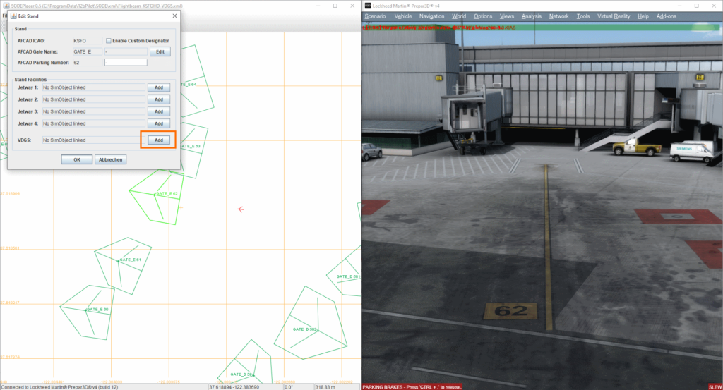
Click the “Add” button on the VDGS slot and then left-click somewhere on the map to place the object. The tool will initially place a default VDGS object (SafeDock T2 model).
Also, to remove a VDGS box from a parking stand, you‘d open the „Edit Stand“ window and click on the appropriate button.
Step 2: Fine tune position of VDGS from within the Simulator
It is time to fire up your simulator and connect the SODE Placer tool to it to enable live placement of the VDGS SimObject.
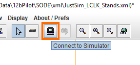
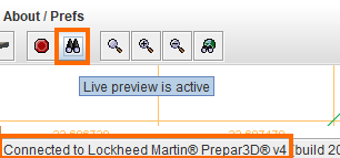
When the tool is connected to the sim (you see the status on the lower left status bar), enable live-preview by clicking on the binocular icon.
You should now be able to see your placed VDGS in the sim.
Note the purple helper lines. They are used to adjust the centerline axis (ground tape) and the vertical tape helps positioning the VDGS box on the terminal wall.
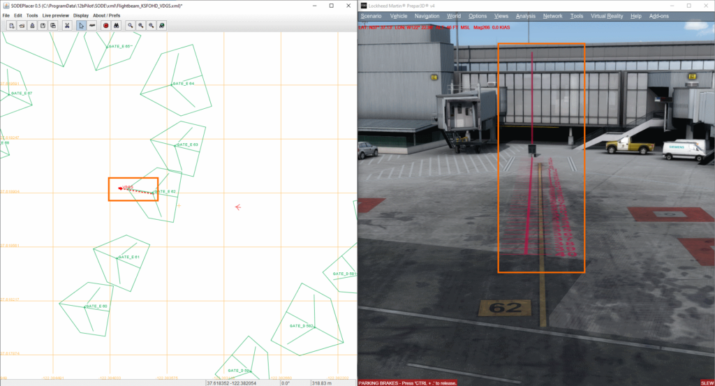
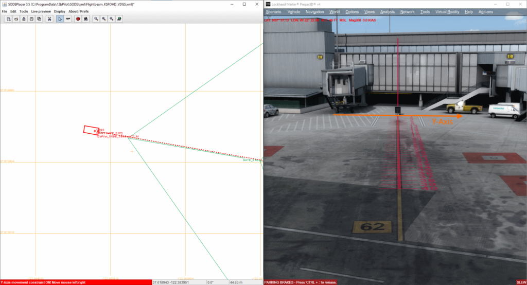
For positioning the VDGS, there exists a special helper mode where you can constrain the movement to the lateral y-Axis and longitudinal x-Axis of the VDGS.
Press the ‘Y’ key and SODEPlacer goes into y-axis constraint mode (red indication on lower left of SODEPlacer). To exit, press ‘Y’ again.
Moving the mouse LEFT or RIGHT will position the VDGS along the y-axis.
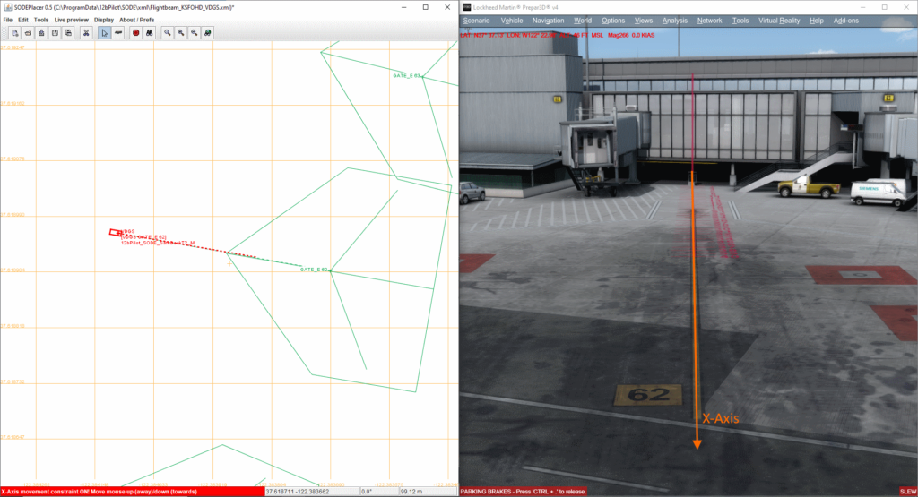
Press the ‘X’ key to activate x-axis constraint mode.
Move the mouse UP or DOWN to place the VDGS along the x-axis until the vertical helper tape reaches the terminal wall.
Of course, if you need to fine tune the heading, use the general mouse inputs available in SODEPlacer:
- Mouse Wheel + CTRL key: Rotate selected object by 1° steps
- Mouse Wheel + SHIFT key: Rotate selected object by 0.1° steps
Once you are happy with the basic placement, save your project!
Step 3: Edit VDGS properties
You can now edit your basic VDGS by double-clicking it, the “Edit VDGS SimObject” menu should appear.
To change the VDGS model, double-click the big area on the right of the menu and select your model.
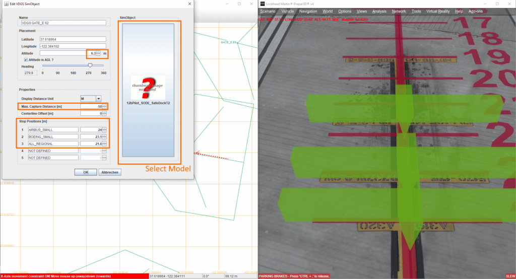
Next step is to adjust the height of the VDGS box. For this, just edit the Altitude property using the mousewheel, the spinners or directly editing the value.
The Max. Capture Distance property is set to 50m per default. This is the distance where the VDGS changes from the capture state (e.g. animated arrows) to the guiding mode.
Stop Positions:
This is a very important step! Here you will assign aircraft types to the individual stop positions. The green helper objects will help you position them in the simulator.
You can either insert individual aircraft type IDs or can use convenient “group designators” for multiple aircraft types. Note that the entries are semi-colon separated without white-space in between, e.g. “ALL_SMALL;MD82;MD83”
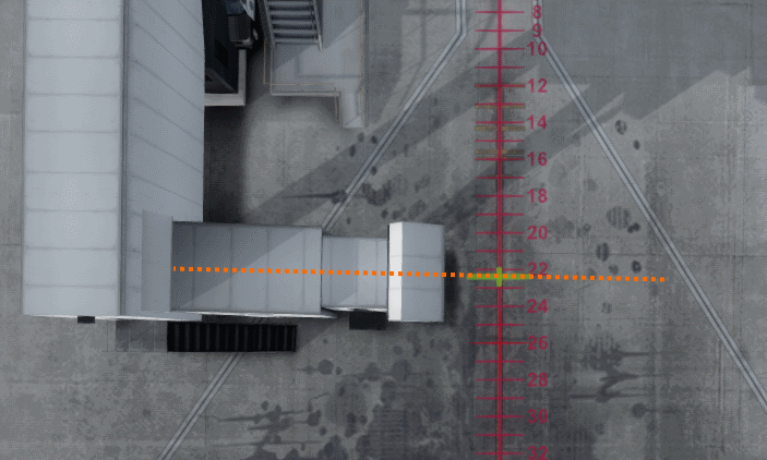
Special Case: T and N type jetways (fixed bridge jetways)
For the fixed bridge type jetways, the stop position is different because for those, SODE takes the aircraft door as a reference and not the nosewheel. You only have to define one single stop position for all aircraft types (i.e. “ALL_ACFT”), and this stop position needs to be positioned on the extended axis of the fixed jetway bridge:
Important! See this separate document for a explanation of the group designators and general rule to follow: VDGS Supported Aircraft Types.
Once you have successfully assigned the aircraft groups/types to the stop lines, save your project!
Step 4: Copy VDGS boxes
Similar to copying jetways to other stands, this is also possible for VDGS, but the ‘SHIFT’ key is used this time.
The copy VDGS feature allows to copy the VDGS and its properties (source parking) to multiple other parking stands (target parkings)!
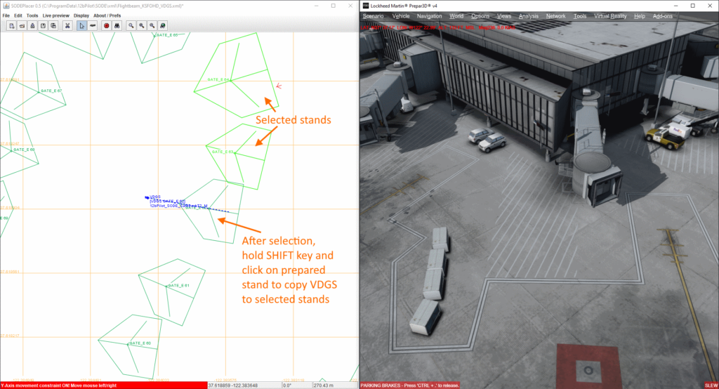
This image will show you have it works:
- Select the stand(s) you want to add the same VDGS box of an already defined stand.
- Hold SHIFT key and click on the prepared stand.
This is the result after SHIFT + Left Mouse-click:
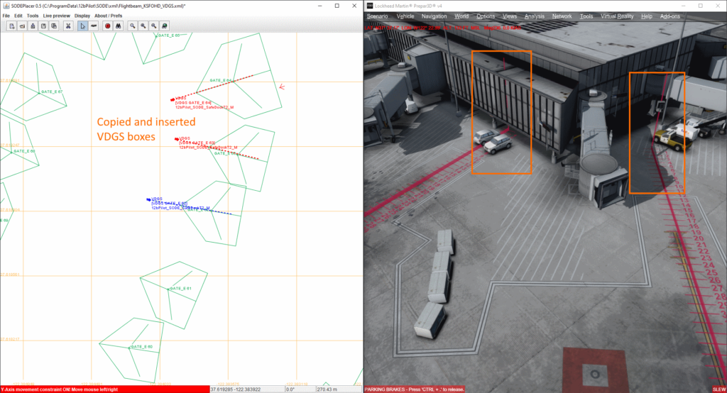
All the target parkings now have the same VDGS boxes with the exact same properties (model, stop line definitions).
Now you only need to fine tune the final positions/headings.
Hint: To move all the stop lines together, you can use SHIFT + Mousewheel when manipulating in the “Edit Stand” menu
This concludes the tutorial.